Unit 5 - Nine Mens
Unit 5: Working to a Brief
Nine Mens Morris (GALT)
Karen - Mathematics
2 Teams:
Producer - Jordan P
Assistant Producer - Harry R
Art - Bryant
Coder - Me/Harry L
Sound - Bryant/Harry R
Design - Bryant/Me
Story - Harry R
Karen Vickers
Students?
Children?
Money?
Research:
Primary:
Secondary:
Nine Men's Morris (also known as Merels, Mills, etc.) is a
strategic board game that was invented during the era of the Roman Empire. It
was also around during Ancient Egyptian times. There are also many other
versions of NMM with altered rules such as Morabaraba, Six Men's Morris and
Twelve Men's Morris.
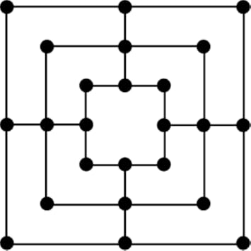
In the game, you play the game with a second player, and you are
each given nine playing pieces. In order to win, you need to either get your
opponent down to having only two playing pieces left or block them from making
any more legal issues in a similar fashion to chess. The game itself takes
place on a board made up of three concentric squares with two corner points and
one midpoint on each of them that are all joined together by straight lines,
adding up to a total of twenty-four points on the entire board (Picture of a
typical Nine Men's Morris board below).
There are two phases in the game, the first of which is the Setup
phase. During this phase, both players take turns in strategically choosing
which eighteen out of twenty-four vacant points to place their nine pieces on
the board.
The second phase is the Regular phase, in which players start
properly playing the game and attacking each other’s pieces. Each turn consists
of the player sliding one of their pieces along the line to a vacant point, and
in order to remove one of the opponent's pieces, the player must create a
string of three pieces on a line. Unless there are no other pieces available,
the player cannot remove a piece that is part of a string. Once a player has only three
pieces left, they can move a piece to any vacant point on the board and not
just an adjacent vacant point. This research will be helpful to me since it
will give me an idea of what rules to program/implement into the game's digital form.
--------------------------------------------------------------------------------------------------------------------------
Wednesday 25th:
Karen comes into the room at 1:30pm
Pitch
SMART Targets:
1.
Date: 29/4/20
Target: Ship exterior model
What to do: Complete a model of the exterior of the ship that the game takes place on within at least a week after receiving concept art for it to work off of.
Progress: Complete.
2.
Date: 06/5/20
Target: Ship interior modelling
What to do: Finish modelling the interior details of the ship by 20th May.
Progress: Started, but ultimately failed due to the complexity of the task, so will instead try to get it done by Monday 25th.
3.
Date: 20/5/20
Target: Ship interior modelling
What to do: Finish modelling the interior details of the ship and UV-mapping the overall model by 25th May.
Progress: Complete, however was instead completed by the end of 27th May due to underestimations.
Development Log
Keypad Model
24/3/20 (continuation of working on the keypad model):

Extruded the faces near the top of the keypad to start forming the anti-glare hood.

Dragged the vertices on the bottom edges of the hood and merged them with the surface vertices.


Duplicated the button mesh to place over the other gaps.
Dragged the bottom of the base downwards for extra thickness.


Cut singular edges in surfaces that wrap around completely in the UV editor.
Unfolded each surface in the UV editor.

Shrunk the completed UVs into the first big square on the map for easier texture photoshopping.

Fully UV-mapped mesh.

The same UV-mapping process is done for each of the buttons.

The buttons are dragged back into place without being combined with the base mesh, and thus, ready for being animated.
Memory Chip Model
8/4/20 (modelling and UV-mapping the memory chip in its entirety):

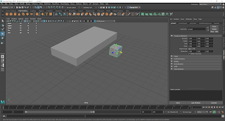
A cube primitive is created.

The cube is then scaled up into a cuboid shape, forming the base of the chip.
Another cube primitive is created.

The cube is then extruded.

Once extrusion is complete, the curves are bevelled in order to look smoother.

The mesh is then scaled appropriately, forming the prongs.

The edges of the base are bevelled.

The prong mesh is duplicated up to 32 times, so that 33 will be on either side.

The end of the base is dragged out to fit all 33 pairs of prongs.

Width of the base is also increased, but again, by dragging out one of the faces so that the first set of prongs stays in relatively the right place.

The prongs are mirrored in order to form the second set, which will be placed on the opposite side.

The two prong sets are then separated from each other for the time being.

A planar UV map is created for the faces on the base.

For any maps that loop around, a random edge on it is cut in order to ensure it unfolds properly.

The maps are then unfolded until they are neat enough so that distortion is reduced as much as possible.

The same process is then carried out for the UVs for the prongson the right...

... as well as the UVs for the prongs on the left, separately. Additionally, once the UV map for one of the prongs on one side are complete, the others on that side are deleted and replaced with new ones with the complete UVs via the aforementioned duplication process.

All the meshes are then combined with each other.
15/4/20 (finishing the memory chip UV):

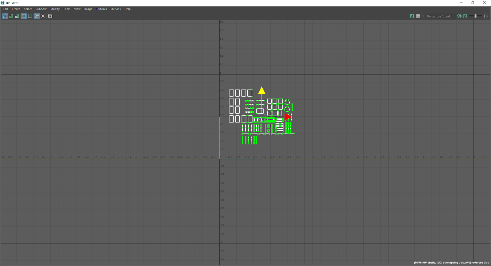
After the meshes are combined, all the UVs in the combined object are then properly separated from each other, ready for texturing.
Control Panel Model
16/4/20 (starting on the control panel model):

Inserted a cube primitive.

Scaled up the cube into a more flat, rectangular shape to form the base of the panel.

Inserted edge loops all over the base for extrusion.

Extruded the faces that form the main screen frames.

Merged the vertices in the corners of the frame in order to make it more edged.

Used the connect tool to connect corner vertices and make the edges look more visible and polished.

Extruded the screen faces out a little bit to more easily separate them from the rest of the base.

Extruded the faces separating the three screens.

The vertices of the frame and the faces separating the screens are merged for additional clean-up.

More edge loops are inserted in order to extrude the faces representing the buttons.

The square faces on the base are extruded, forming the buttons.

The multi-cut tool is then used to create octagon-shaped faces in the base.
17/4/20 (continuing with the control panel):

Two of the vertices in each octagon face are properly connected once cutting is complete due to the cutting failing to register otherwise.

Excessive edges are then deleted and the octagon faces are extruded.

The front faces are then scaled down on all axes to form a more frustum-like shape and thus make them look more like dials.

Even more edge loops are inserted in order to create the faces that represent the sliders.

The faces representing the frame of the sliders are then extruded..

...followed by the faces representing the sliders themselves.
20/4/20 (finishing with the actual modelling process for the control panel):

Edge loops are inserted near the bottoms of the dials.

The new faces formed by this are then extruded to complete the dials by making them stick out from the base more.
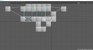
22/4/20 (applying final cleanup and UV-mapping to the control panel):

Excessive vertices and edges are removed from the back of the base.

A planar UV is created for each surface on the mesh.

If the surface loops around, a random edge is cut in the UV editor in order to ensure the map is completely flat upon unfolding.

The map is then unfolded and all UV distortion on that respective surface is removed.

Additional edge/vertex cleanup is carried out on the slider frames.

Once all the surfaces on the control panel have been UV-mapped, they are then organised and grouped together and scaled down to fit into one big square on the graph. From there, the model is ready to be textured.
Ship Model (exterior)
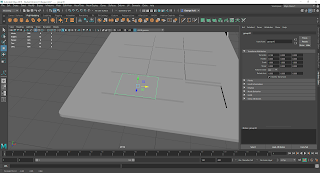
6/5/20 (beginning work on the exterior of the ship model):

Inserted a sphere primitive.

Dragged out and scaled out parts of the circle in order to create a more spaceship-like shape.

Faces on the back of the mesh are deleted.

The hole is then filled back in with the fill tool...

Vertices on either side of the face are then joined together via the component connector tool in order to form new vertices, whilst still ensuring that the centre surface is flat.

The same face is then scaled and positioned to match the intended shape.

Vertices along the edge of the top surface are positioned in order to form a straight set of edges.

The top surface is then deleted and filled back in for flatness.

Excess vertices are then deleted as part of cleanup.

The mesh is then scaled up in order to match the intended proportions (so that it is in accordance to concept art).
11/5/20 (continuing with the ship exterior):

Circular edge loops are formed by vertices which are created with the multi-cut tool.

The circles formed from multi-cutting are then extruded.

The surfaces on the tops of the extruded circles are then deleted and re-filled.

These faces are then poked..

..and dragged out in order to make the surfaces look flatter and more organised when they are deleted again.

Once the surfaces are re-deleted, the edge loops on the ends of each cylinder are scaled outwards from each other in order to look more separated from each other.

Through the use of the edge loop insertion tool, edge loops are inserted on the front of the mesh.

The vertices on the top ends of both pairs of loops are joined together via the component connection tool.

The surfaces in between these inserted loops are then extruded inwards a little bit, thus forming the ship's windows.

With the windows extruded, the connections inserted earlier are deleted as part of clean-up.
 More edge loops are inserted on the side of the mesh.

Gaps in the edge loops are then joined together via vertex connecting.
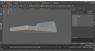
12/5/20-13/5/20 (finishing the ship exterior):

The edge loops on the insides of the cylinders on the back are extruded inwards..

..and the vertices on the end of each edge are merged together so that the holes are properly filled in.

The centre vertices of certain surfaces are dragged into the edges and vertex merged into them.

Sometimes, these centre vertices are chambered via the vertex chamber tool before being merged in order to properly close the holes.
 Now that the holes are completely filled in, the thrusters of the ship are now fully formed.

The edge loop on the bottom end the base of the ship is extruded in order to ensure that the sides of the ship are at 90-degree angles.

The edges on the ship's side inserted from earlier are then re-positioned accordingly.

More edges are inserted via multi-cutting in order to extrude more faces. From there, the selected faces on the side of the ship are detached from the overall mesh, forming the docking bay door.

The model is moved upwards from the grid.

The faces formed earlier by multi-cutting are then extruded..

..and the top surface is then bevelled for smoothness.
19/5/20 (starting on the ship interior):

A cube primitive is inserted.

The cube primitive is then positioned inside the ship model, flattened and scaled to the width of the ship.

After being turned into a flat rectangle inside the ship model, the cube is extruded multiple times in order to match the shape of the ship, thus forming the ship floor.

This is then combined with the ship model via the combine tool and its vertices are merged with those that are part of the original ship mesh and also adjacent to the floor's vertices in order to seal the gaps properly.
20/5/20 (continuing work on the ship interior):
 Edge loops are inserted on the other side of the ship.

An entire edge loop across the top of the front of the ship is created via the multi-cut tool.

The same is done for between the walls separating the windows.

Another edge loop is inserted around the top middle of the ship.

Faces on the insides of the walls of the ship are extruded in order to help form the interior walls separating the different rooms/sections of the ship.
24/5/20 (continuing working on the ship interior):

Faces on the front and back of each outer extrusion are deleted so that new, cleaner faces can be created.

The insides of the walls separating the docking bay, open space and sleeping quarters are covered up via extrusion and vertex merging.

The segment of the floor separating the areas mentioned above and the cargo bay is extruded upwards.

Vertices are then inserted along the edges of the walls via multi-cutting and merged with the cargo bay wall's vertices.
25/5/20 (continuing work on the ship interior):

Edges along the inside of the wall are deleted as part of cleanup.

The faces on the outside of the other walls are also deleted.

Edge of the floor of the hallway leading to the bridge is extruded.

Vertices are cut along the edge of this extrusion..

..and merged with those of the bottoms of the walls separating the rooms across the middle of the ship.

The process from earlier is then repeated with this face being extruded upwards..
26/5/20 (continuing work on the ship interior):

..and vertices being cut in the adjacent edges for merging in order to close gaps properly.

Once again, the edges created on the insides of the walls are deleted for cleanup.

More edges are inserted along the top of the windows via multi-cutting and edge loop insertion as a marker indicating where the extrusions for the walls separating the Captain's quarters, cockpit and break room will take place on the floor faces.


Using this indicator, the edges that are planned to be extruded are created via multi-cutting.

Multiple faces near the edge of this surface are extruded slightly upwards in order to properly form the cockpit.
 Because of this, the vertices on the edge of the cockpit floor are merged with those on the window frames in order to maintain the ship's original shape.
27/5/20 (finishing work on the ship interior and starting on UVs):

A face on the cockpit floor within one of the window frames is extruded in order to fill it in..

..and its vertices are merged with the outside surfaces so that once again, the gaps are properly filled.
 Due to being short for time, this process went unfinished. Thus, the edges and vertices created as guidelines are deleted for cleanup.

A planar UV map is created for each surface on the ship mesh.

The map is then unfolded until it is as flat as it can possibly be, thus greatly reducing texture distortion.

Additionally, if the surface loops around, one of the edges is cut so that the map can be unfolded properly.
28/5/20 (finishing the ship UVs, as well as the overall model):

Once all of the maps are created and unfolded, they are all neatly grouped together, selected and scaled down in order to fit in one big square on the grid.


The same process is then repeated for the docking bay door, which is a separate model. From here, the ship is now as complete as it could have gotten within the time frame and ready to be textured.
SMART Targets:
1.
Date: 29/4/20
Target: Ship exterior model
What to do: Complete a model of the exterior of the ship that the game takes place on within at least a week after receiving concept art for it to work off of.
Progress: Complete.
2.
Date: 06/5/20
Target: Ship interior modelling
What to do: Finish modelling the interior details of the ship by 20th May.
Progress: Started, but ultimately failed due to the complexity of the task, so will instead try to get it done by Monday 25th.
3.
Date: 20/5/20
Target: Ship interior modelling
What to do: Finish modelling the interior details of the ship and UV-mapping the overall model by 25th May.
Progress: Complete, however was instead completed by the end of 27th May due to underestimations.
Development Log
Keypad Model
24/3/20 (continuation of working on the keypad model):

Extruded the faces near the top of the keypad to start forming the anti-glare hood.

Dragged the vertices on the bottom edges of the hood and merged them with the surface vertices.

Angled the top of the hood.

Inserted an edge loop on the back of the hood.

Dragged the edge loop outward to make the hood look more curved.
31/3/20 (completing the actual modelling process for the keypad):


Dragged the bottom of the base downwards for extra thickness.
1/4/20 (UV-mapping the keypad and its buttons):

Created planar UV Maps for each for each surface on the mesh.


Unfolded each surface in the UV editor.

Shrunk the completed UVs into the first big square on the map for easier texture photoshopping.

Fully UV-mapped mesh.

The same UV-mapping process is done for each of the buttons.

The buttons are dragged back into place without being combined with the base mesh, and thus, ready for being animated.
Memory Chip Model
8/4/20 (modelling and UV-mapping the memory chip in its entirety):

A cube primitive is created.

The cube is then scaled up into a cuboid shape, forming the base of the chip.

Another cube primitive is created.

The cube is then extruded.

Once extrusion is complete, the curves are bevelled in order to look smoother.

The mesh is then scaled appropriately, forming the prongs.

The edges of the base are bevelled.

The prong mesh is duplicated up to 32 times, so that 33 will be on either side.

The end of the base is dragged out to fit all 33 pairs of prongs.

Width of the base is also increased, but again, by dragging out one of the faces so that the first set of prongs stays in relatively the right place.
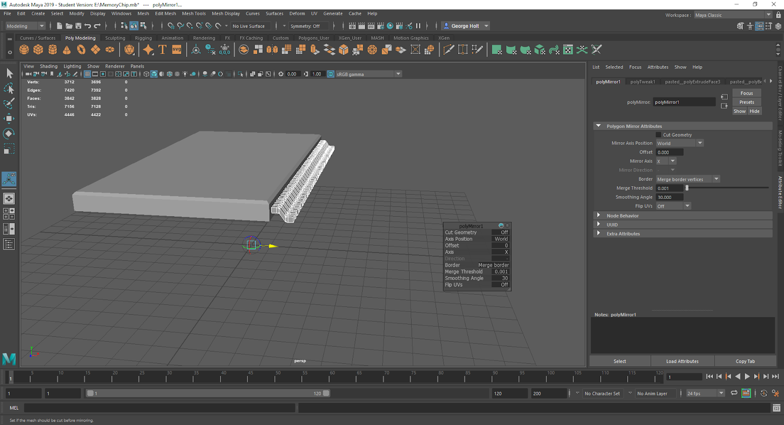
The prongs are mirrored in order to form the second set, which will be placed on the opposite side.

The two prong sets are then separated from each other for the time being.

A planar UV map is created for the faces on the base.

For any maps that loop around, a random edge on it is cut in order to ensure it unfolds properly.

The maps are then unfolded until they are neat enough so that distortion is reduced as much as possible.

The same process is then carried out for the UVs for the prongson the right...

... as well as the UVs for the prongs on the left, separately. Additionally, once the UV map for one of the prongs on one side are complete, the others on that side are deleted and replaced with new ones with the complete UVs via the aforementioned duplication process.

All the meshes are then combined with each other.
15/4/20 (finishing the memory chip UV):

After the meshes are combined, all the UVs in the combined object are then properly separated from each other, ready for texturing.
Control Panel Model
16/4/20 (starting on the control panel model):

Inserted a cube primitive.

Scaled up the cube into a more flat, rectangular shape to form the base of the panel.

Inserted edge loops all over the base for extrusion.

Extruded the faces that form the main screen frames.

Merged the vertices in the corners of the frame in order to make it more edged.

Used the connect tool to connect corner vertices and make the edges look more visible and polished.

Extruded the screen faces out a little bit to more easily separate them from the rest of the base.

Extruded the faces separating the three screens.

The vertices of the frame and the faces separating the screens are merged for additional clean-up.

More edge loops are inserted in order to extrude the faces representing the buttons.

The square faces on the base are extruded, forming the buttons.

The multi-cut tool is then used to create octagon-shaped faces in the base.
17/4/20 (continuing with the control panel):

Two of the vertices in each octagon face are properly connected once cutting is complete due to the cutting failing to register otherwise.

Excessive edges are then deleted and the octagon faces are extruded.

The front faces are then scaled down on all axes to form a more frustum-like shape and thus make them look more like dials.

Even more edge loops are inserted in order to create the faces that represent the sliders.

The faces representing the frame of the sliders are then extruded..

...followed by the faces representing the sliders themselves.
20/4/20 (finishing with the actual modelling process for the control panel):

Edge loops are inserted near the bottoms of the dials.

The new faces formed by this are then extruded to complete the dials by making them stick out from the base more.
22/4/20 (applying final cleanup and UV-mapping to the control panel):

Excessive vertices and edges are removed from the back of the base.

A planar UV is created for each surface on the mesh.

If the surface loops around, a random edge is cut in the UV editor in order to ensure the map is completely flat upon unfolding.

The map is then unfolded and all UV distortion on that respective surface is removed.

Additional edge/vertex cleanup is carried out on the slider frames.
Once all the surfaces on the control panel have been UV-mapped, they are then organised and grouped together and scaled down to fit into one big square on the graph. From there, the model is ready to be textured.
Ship Model (exterior)
6/5/20 (beginning work on the exterior of the ship model):

Inserted a sphere primitive.

Dragged out and scaled out parts of the circle in order to create a more spaceship-like shape.

Faces on the back of the mesh are deleted.

The hole is then filled back in with the fill tool...

Vertices on either side of the face are then joined together via the component connector tool in order to form new vertices, whilst still ensuring that the centre surface is flat.

The same face is then scaled and positioned to match the intended shape.

Vertices along the edge of the top surface are positioned in order to form a straight set of edges.

The top surface is then deleted and filled back in for flatness.

Excess vertices are then deleted as part of cleanup.

The mesh is then scaled up in order to match the intended proportions (so that it is in accordance to concept art).
11/5/20 (continuing with the ship exterior):

Circular edge loops are formed by vertices which are created with the multi-cut tool.

The circles formed from multi-cutting are then extruded.

The surfaces on the tops of the extruded circles are then deleted and re-filled.

These faces are then poked..

..and dragged out in order to make the surfaces look flatter and more organised when they are deleted again.

Once the surfaces are re-deleted, the edge loops on the ends of each cylinder are scaled outwards from each other in order to look more separated from each other.

Through the use of the edge loop insertion tool, edge loops are inserted on the front of the mesh.

The vertices on the top ends of both pairs of loops are joined together via the component connection tool.

The surfaces in between these inserted loops are then extruded inwards a little bit, thus forming the ship's windows.

With the windows extruded, the connections inserted earlier are deleted as part of clean-up.


Gaps in the edge loops are then joined together via vertex connecting.
12/5/20-13/5/20 (finishing the ship exterior):

The edge loops on the insides of the cylinders on the back are extruded inwards..

..and the vertices on the end of each edge are merged together so that the holes are properly filled in.

The centre vertices of certain surfaces are dragged into the edges and vertex merged into them.

Sometimes, these centre vertices are chambered via the vertex chamber tool before being merged in order to properly close the holes.


The edge loop on the bottom end the base of the ship is extruded in order to ensure that the sides of the ship are at 90-degree angles.

The edges on the ship's side inserted from earlier are then re-positioned accordingly.

More edges are inserted via multi-cutting in order to extrude more faces. From there, the selected faces on the side of the ship are detached from the overall mesh, forming the docking bay door.

The model is moved upwards from the grid.

The faces formed earlier by multi-cutting are then extruded..

..and the top surface is then bevelled for smoothness.
19/5/20 (starting on the ship interior):

A cube primitive is inserted.

The cube primitive is then positioned inside the ship model, flattened and scaled to the width of the ship.

After being turned into a flat rectangle inside the ship model, the cube is extruded multiple times in order to match the shape of the ship, thus forming the ship floor.

This is then combined with the ship model via the combine tool and its vertices are merged with those that are part of the original ship mesh and also adjacent to the floor's vertices in order to seal the gaps properly.
20/5/20 (continuing work on the ship interior):


An entire edge loop across the top of the front of the ship is created via the multi-cut tool.

The same is done for between the walls separating the windows.

Another edge loop is inserted around the top middle of the ship.

Faces on the insides of the walls of the ship are extruded in order to help form the interior walls separating the different rooms/sections of the ship.
24/5/20 (continuing working on the ship interior):

Faces on the front and back of each outer extrusion are deleted so that new, cleaner faces can be created.

The insides of the walls separating the docking bay, open space and sleeping quarters are covered up via extrusion and vertex merging.

The segment of the floor separating the areas mentioned above and the cargo bay is extruded upwards.

Vertices are then inserted along the edges of the walls via multi-cutting and merged with the cargo bay wall's vertices.
25/5/20 (continuing work on the ship interior):

Edges along the inside of the wall are deleted as part of cleanup.

The faces on the outside of the other walls are also deleted.

Edge of the floor of the hallway leading to the bridge is extruded.

Vertices are cut along the edge of this extrusion..

..and merged with those of the bottoms of the walls separating the rooms across the middle of the ship.

The process from earlier is then repeated with this face being extruded upwards..
26/5/20 (continuing work on the ship interior):

..and vertices being cut in the adjacent edges for merging in order to close gaps properly.

Once again, the edges created on the insides of the walls are deleted for cleanup.

More edges are inserted along the top of the windows via multi-cutting and edge loop insertion as a marker indicating where the extrusions for the walls separating the Captain's quarters, cockpit and break room will take place on the floor faces.


Using this indicator, the edges that are planned to be extruded are created via multi-cutting.

Multiple faces near the edge of this surface are extruded slightly upwards in order to properly form the cockpit.

27/5/20 (finishing work on the ship interior and starting on UVs):

A face on the cockpit floor within one of the window frames is extruded in order to fill it in..

..and its vertices are merged with the outside surfaces so that once again, the gaps are properly filled.


A planar UV map is created for each surface on the ship mesh.

The map is then unfolded until it is as flat as it can possibly be, thus greatly reducing texture distortion.

Additionally, if the surface loops around, one of the edges is cut so that the map can be unfolded properly.
28/5/20 (finishing the ship UVs, as well as the overall model):

Once all of the maps are created and unfolded, they are all neatly grouped together, selected and scaled down in order to fit in one big square on the grid.


The same process is then repeated for the docking bay door, which is a separate model. From here, the ship is now as complete as it could have gotten within the time frame and ready to be textured.

show in here your personal development in your role. what you are actually doing.
ReplyDelete